IMCOMPLETE
This tutorial will go with the assumption that you have made an account and paid of the Fritzing software and will be using the part found in 4:08 of the arduino Series to create. An attempt will be made to allow for compatibility of older (and free) versions of Fritzing.
Unlike other tutorials, this one will differ as we will be making the part from scratch. There are standards we must follow like colors and fonts. All units in metric, I will refrain from using imperial ("i" for inferior).Click here for the official reference
I am not confident enough of this tutorial for products made following this instructions to be used to make PCB from PCB manufacturers. This page will be constantly updated with instructions until this warning is removed. It is only to be used for making and planning circuits that you have designed.
Vector Graphics Software to use
In order to edit and save .SVG files we must use a vector graphics editor. A small sample of options are:
I will be utalise inkscape for the reason for its immediate accessibility due to it being free. All concepts introduced will be (i assume) easily accessed in other softwares, as you will see. To download the latest version for your OS click here or simply search for Inkscape and click on the link that has "inscape.org" in it.
About the files to be created
There are 4 files required to upload to the custom component menu of fritzing
To access this menu select a component the quickest way is to right click on part in the part menu and select "edit part (new parts editor)". You could also drag a part to breadboard view then click on; Part -> Edit (new parts editor), and the same menu for the same part will pop up.
For simplicity's sake, i will be combining the breadboard view and icon view into on file with the alias "xxx"_breadboard_icon. I have not encountered any problems.
Creating the files
Begin by noting the 2D dimensions.
Since I will be using the SSD1306 128x64 OLED display as my example:
Breadboard/Icon SVG file
Here is where your artistic talent comes into play, I personally have none. I keep my graphics simple enough for it to be recognised; rectangles of different
sizes and colours. Since this is your part, what is crucial is to get the lengths correct.
Ensure all units in software are in "mm".
If you did not read the Fritzing Official Standard page, just use "Droid Sands" for everthing other than ICs, which you would use "OCR A".
Download these fonts from their page linked up. ALSO READ IT.
You can download this reference I have put together to allow faster construction of pins and general parts found in modules/components for the Breadboard/Icon View.
Of the reasons that I have composed the file above is to maintain the spacing between pins which is 2.54mm with 0.762 mm thickness
Steps go as follows:
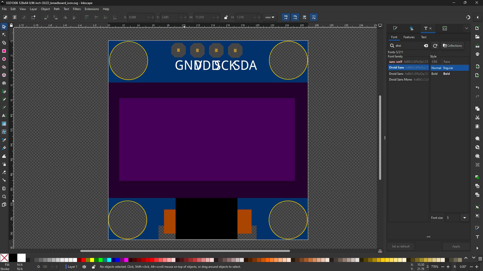
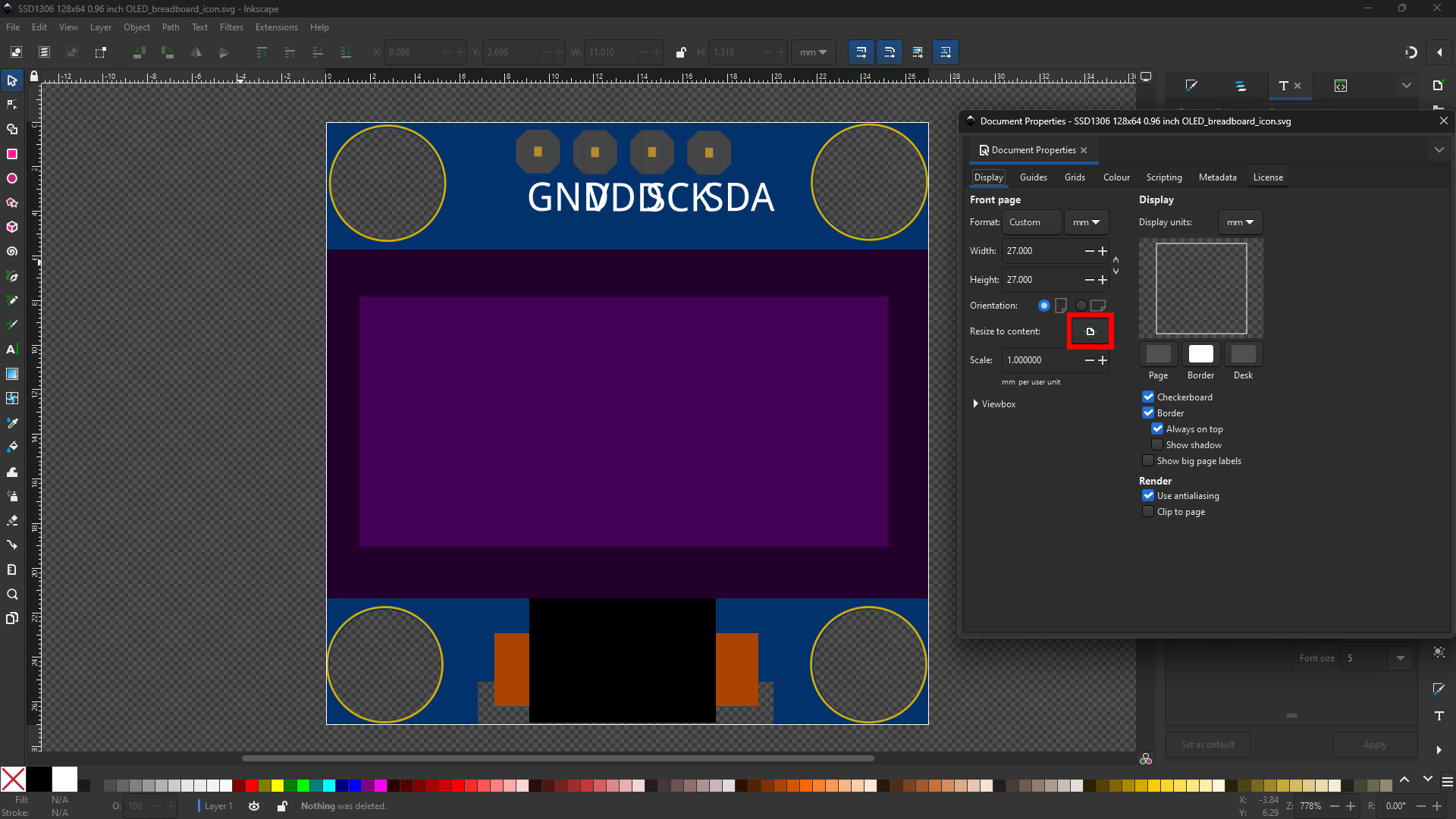
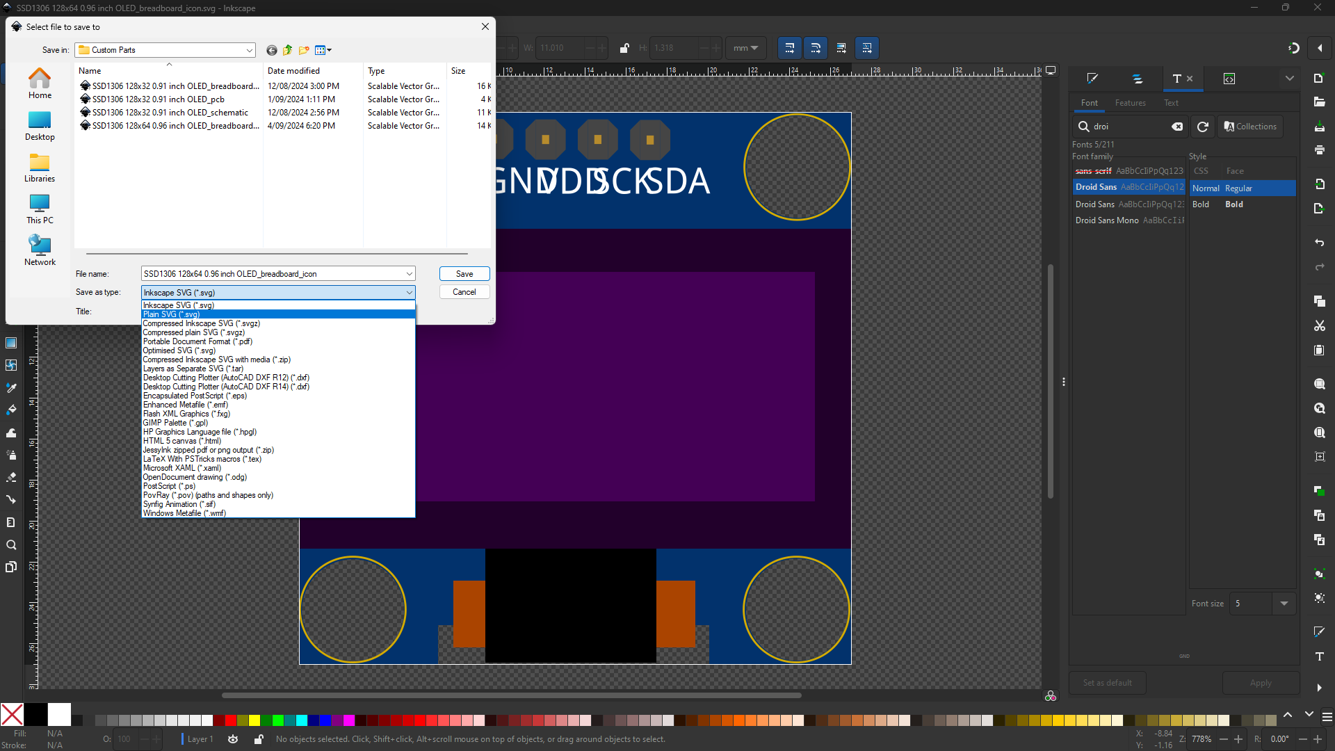
Notice the sizing of the text. Im using Droid Sans, as I've mentioned before, however after uploading this file to the Breadboard Viewer, the alignment changes and as of now I do not know of the reason. I will update this page once I have found a solution.
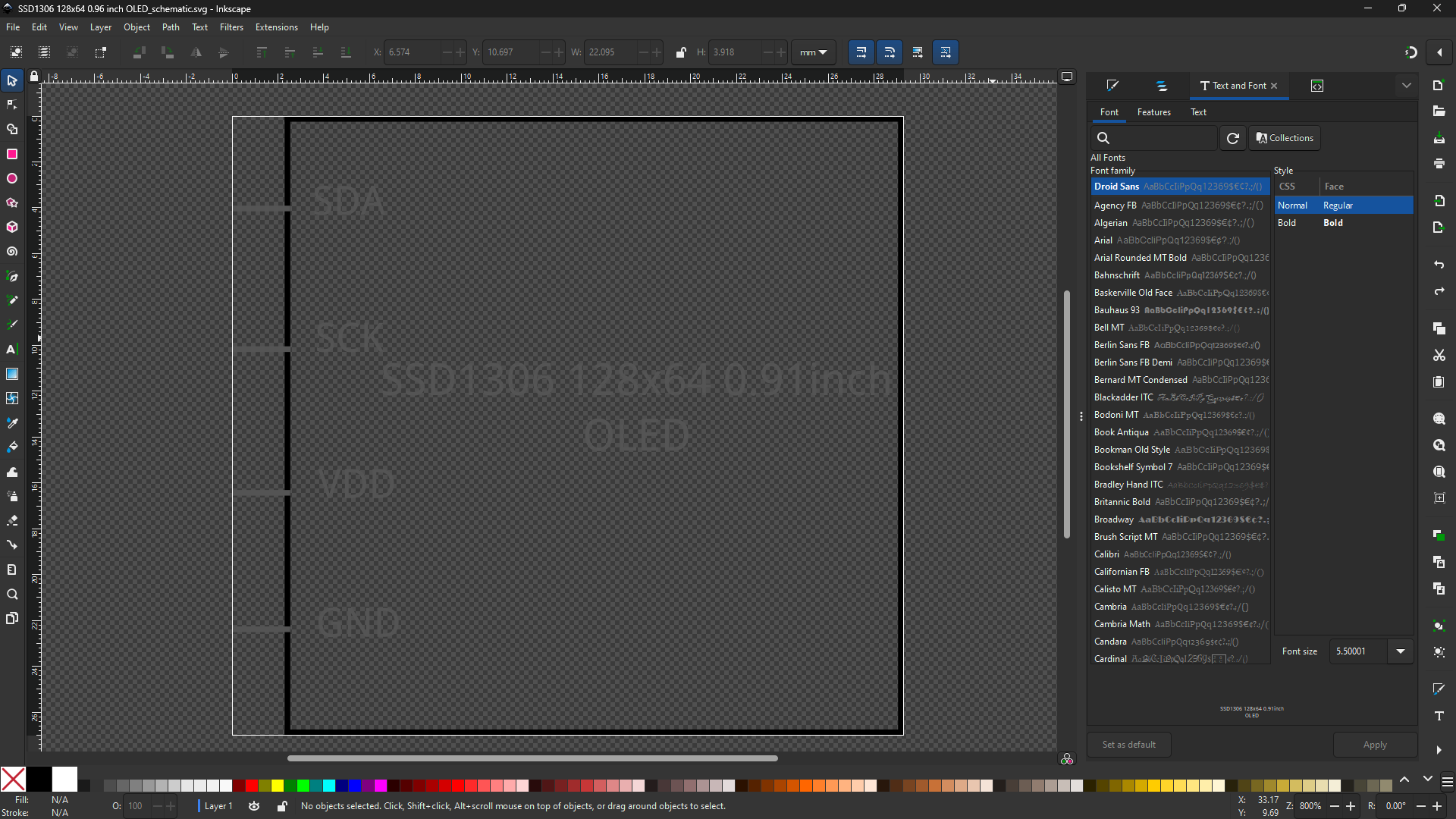
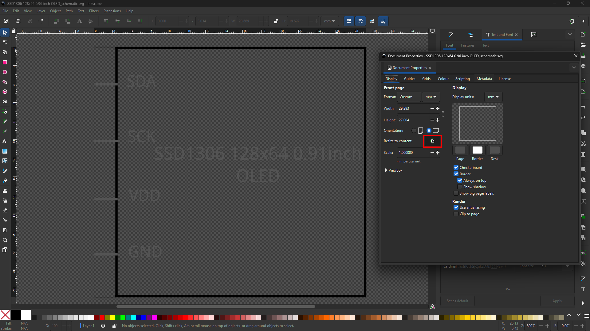
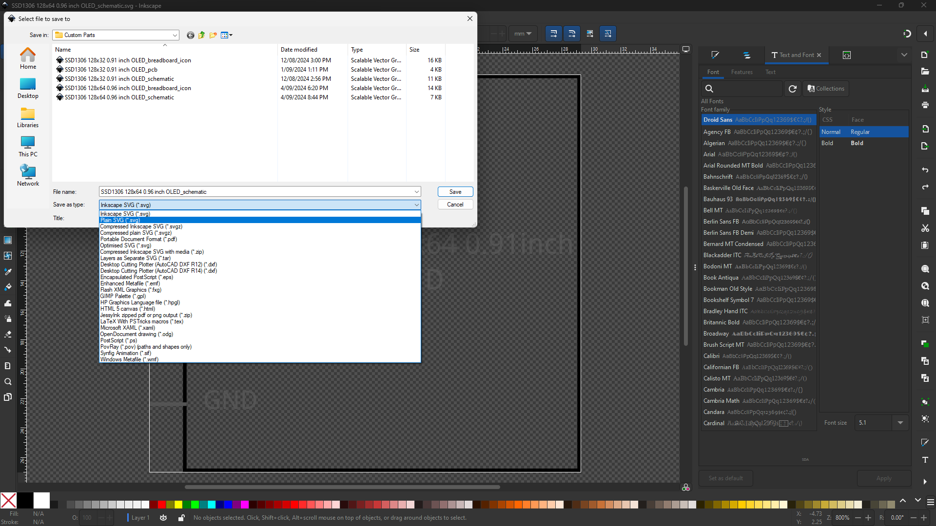
Schematic SVG file
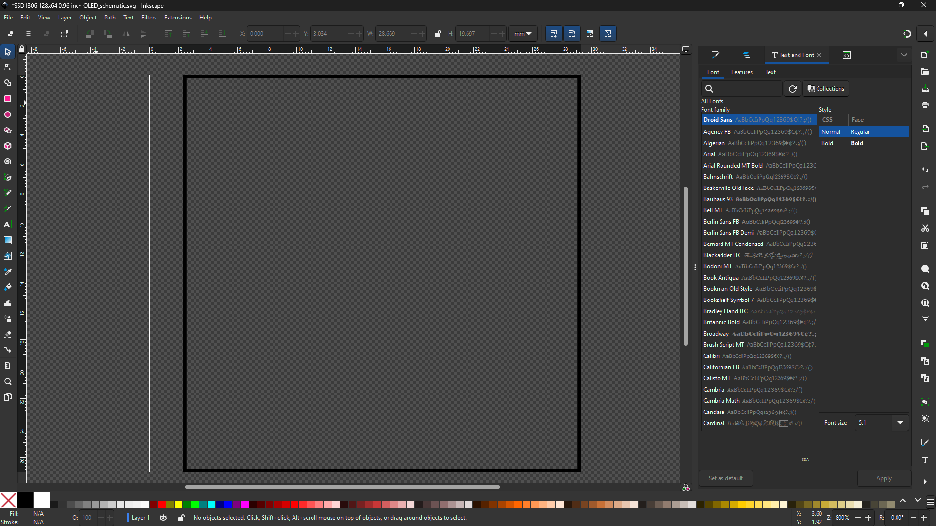
The simplest of the files.
Steps go as follows:
PCB SVG file
The PCB file requires the most technical work. Download this file to get standard icons for fast construction of this file.
There should be no text
Steps go as follows:
- ,
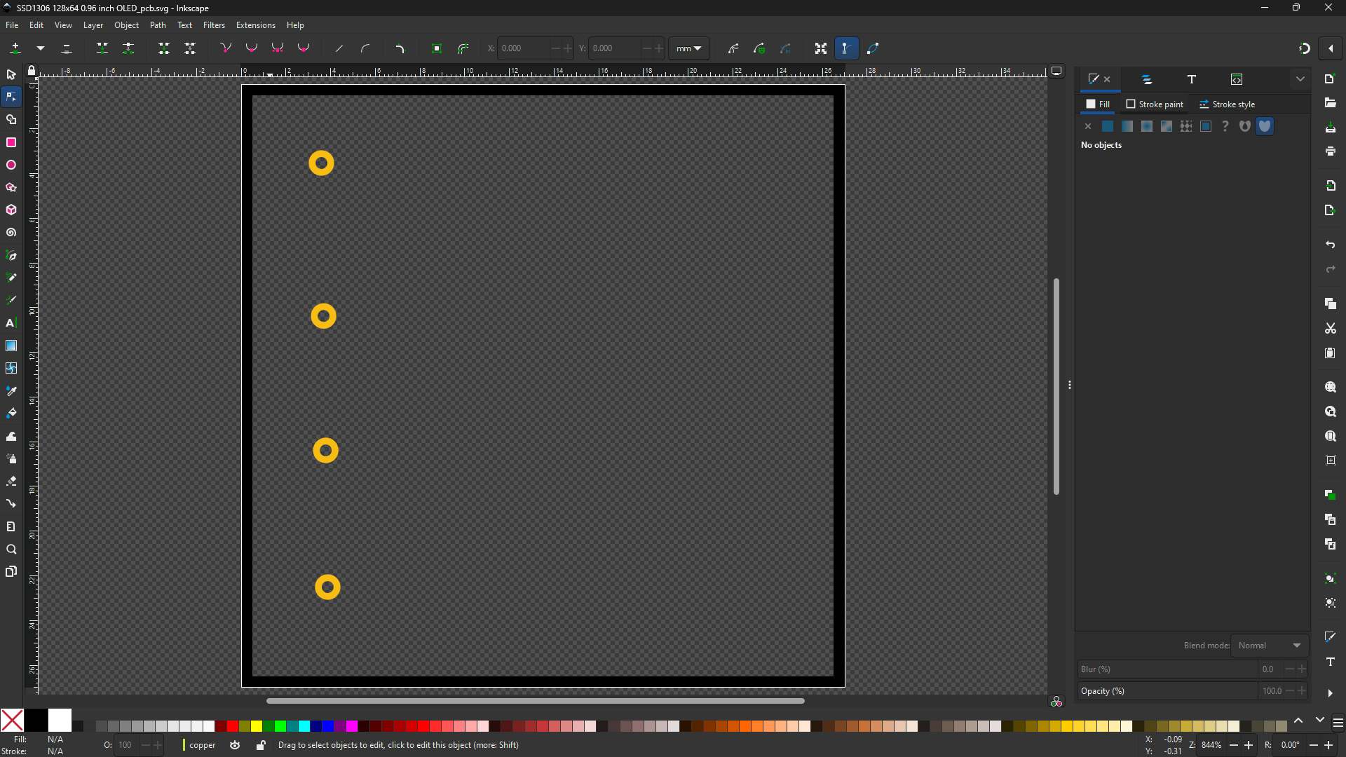
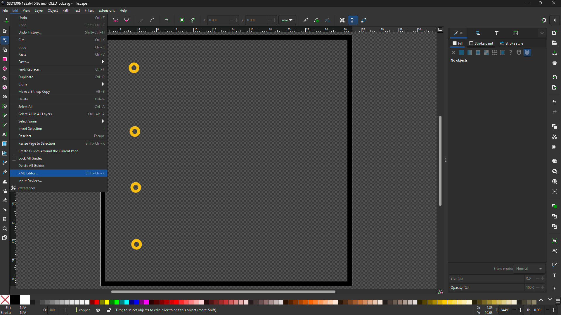
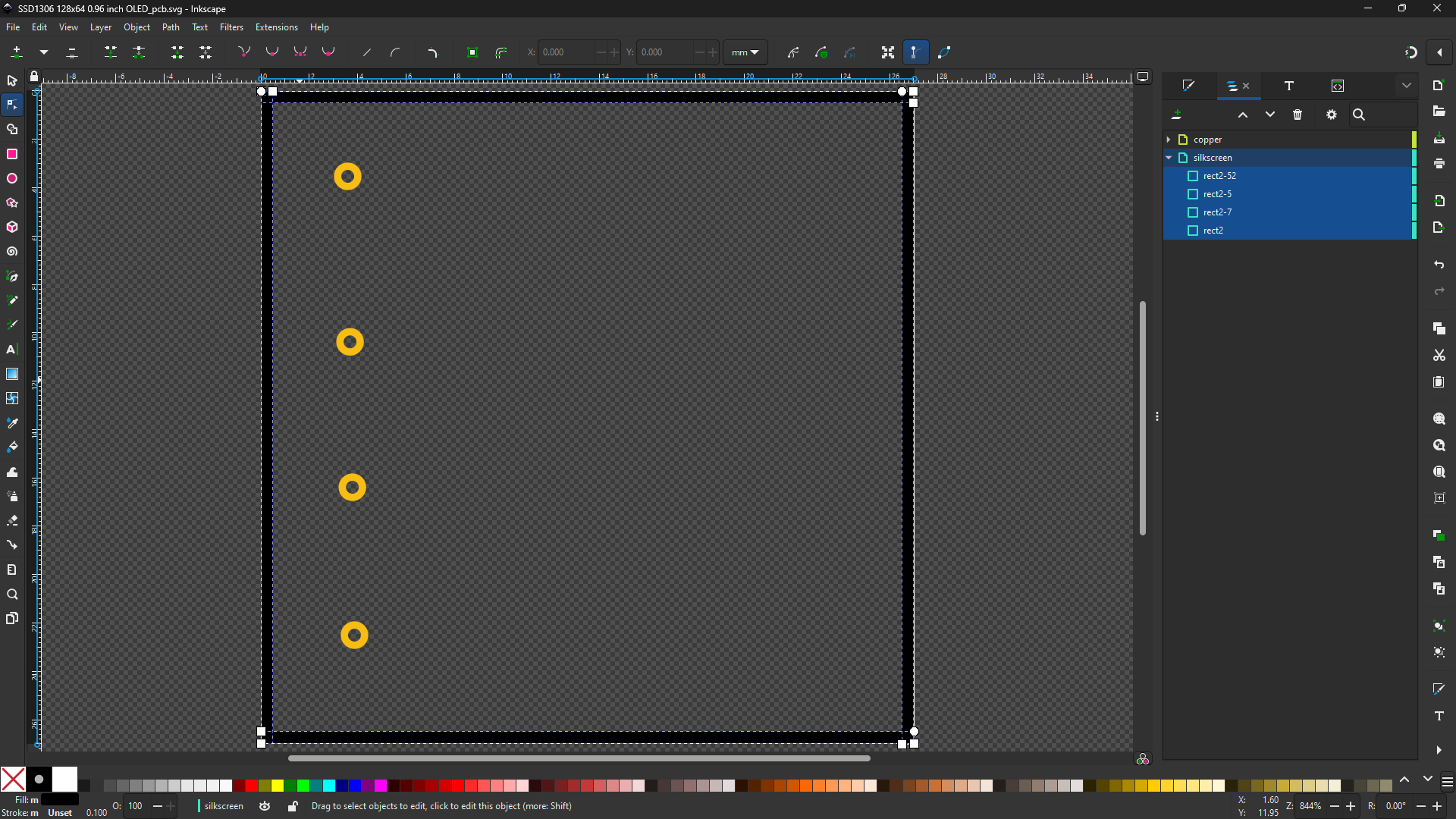
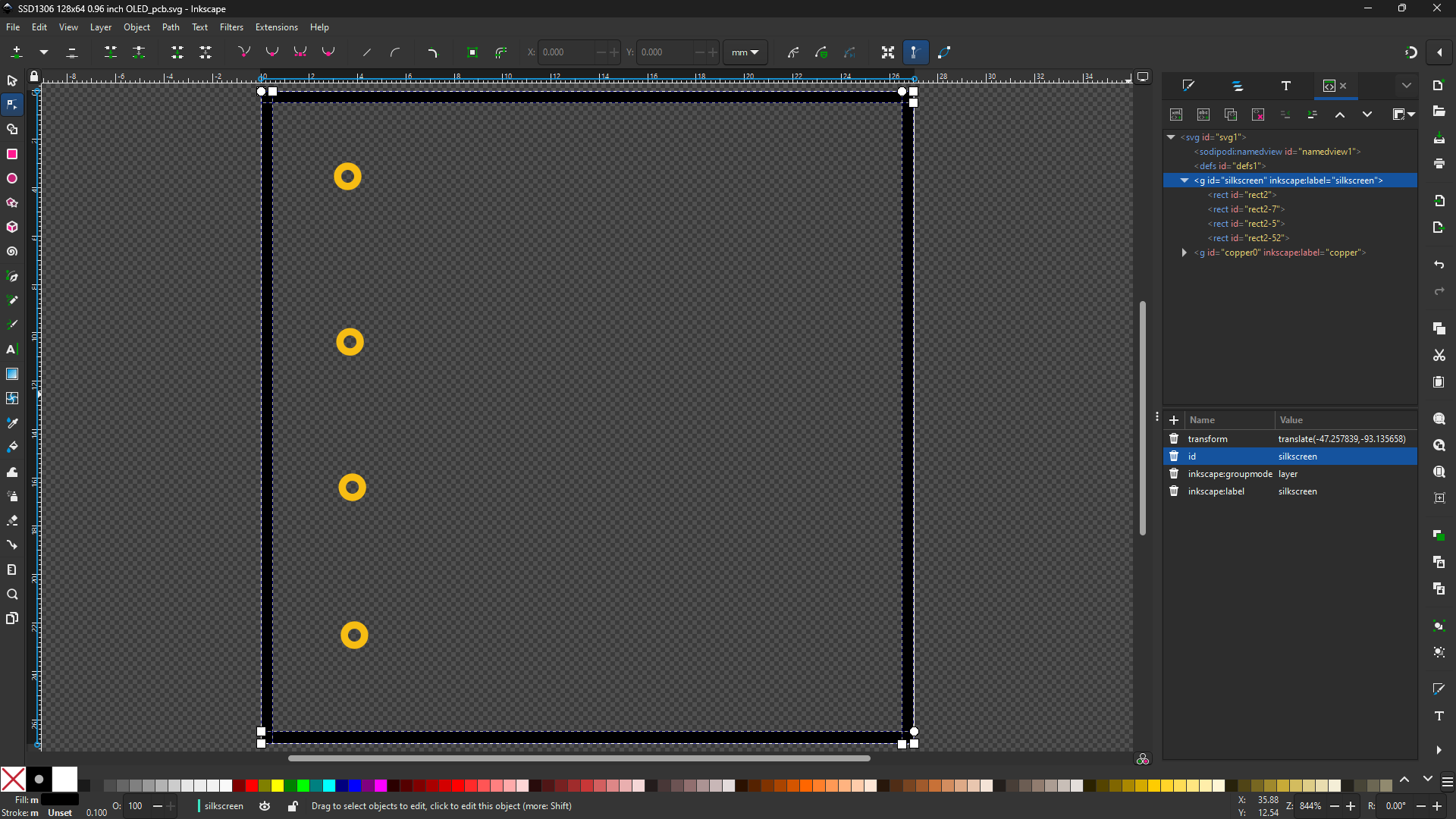
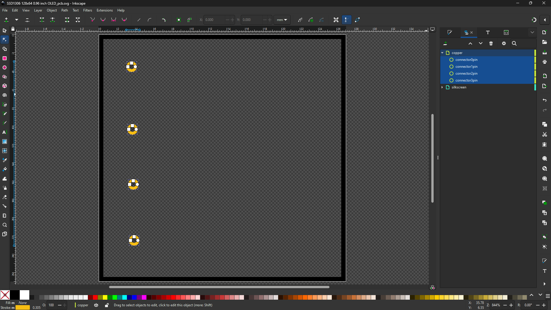
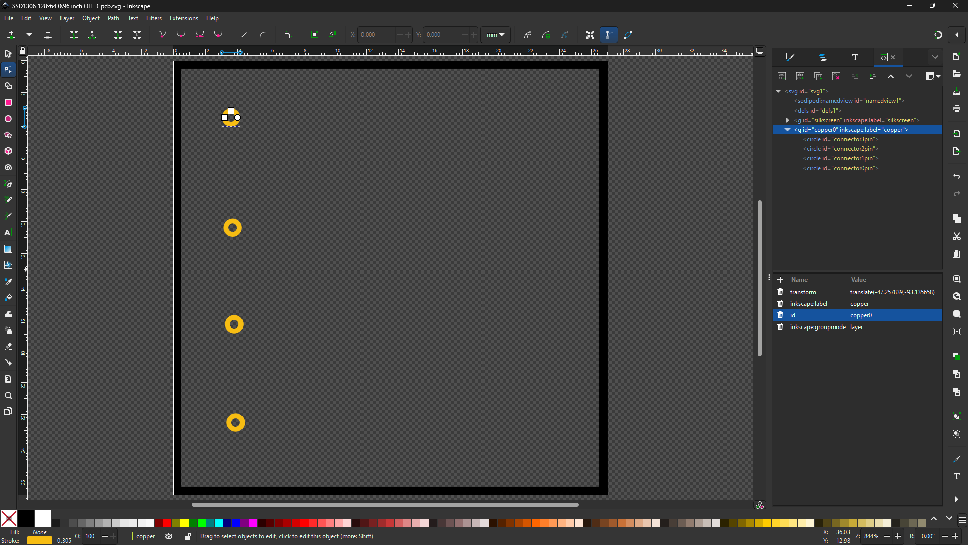
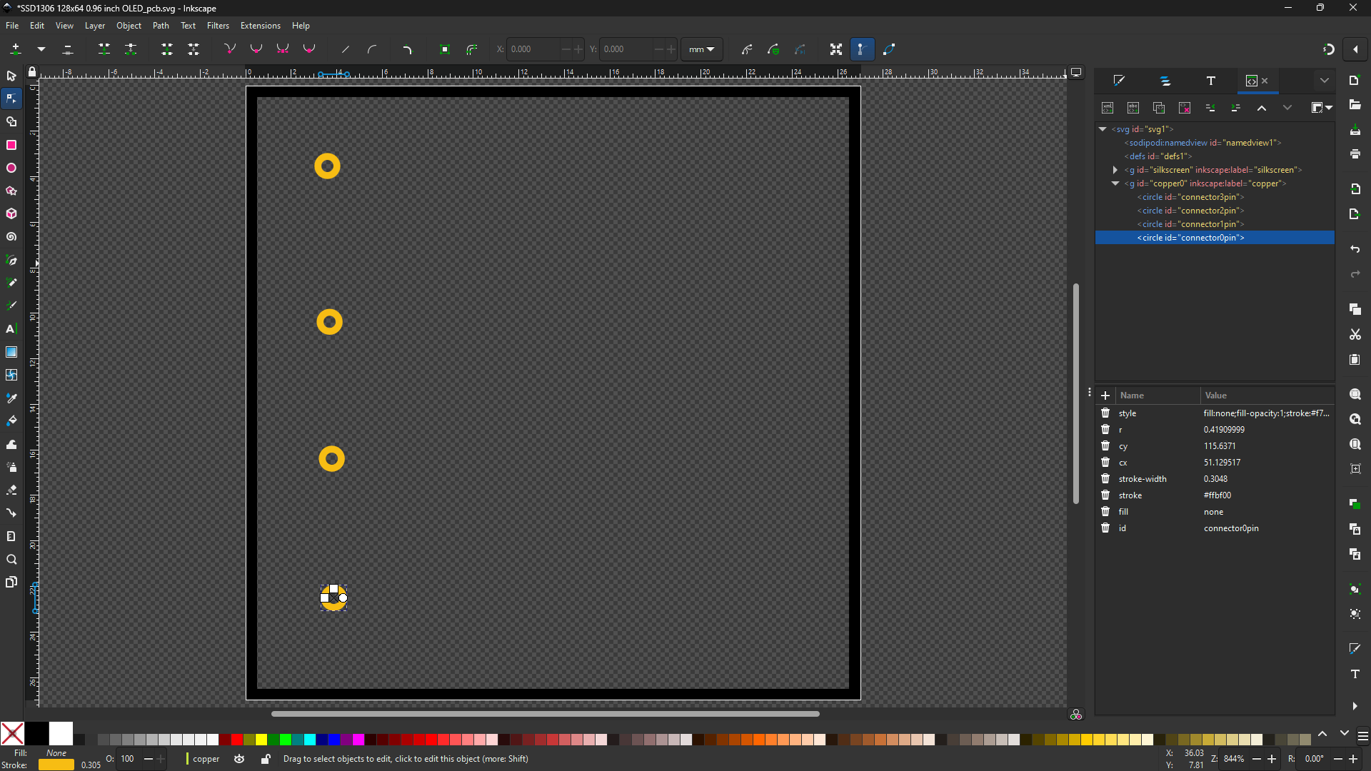
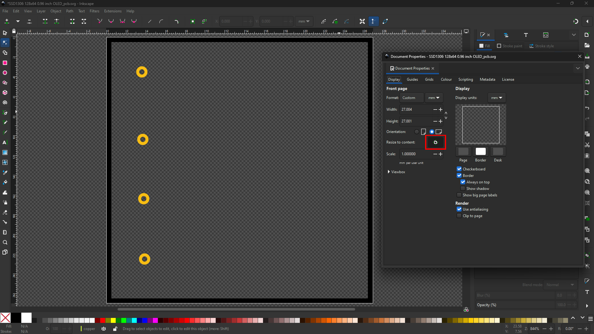
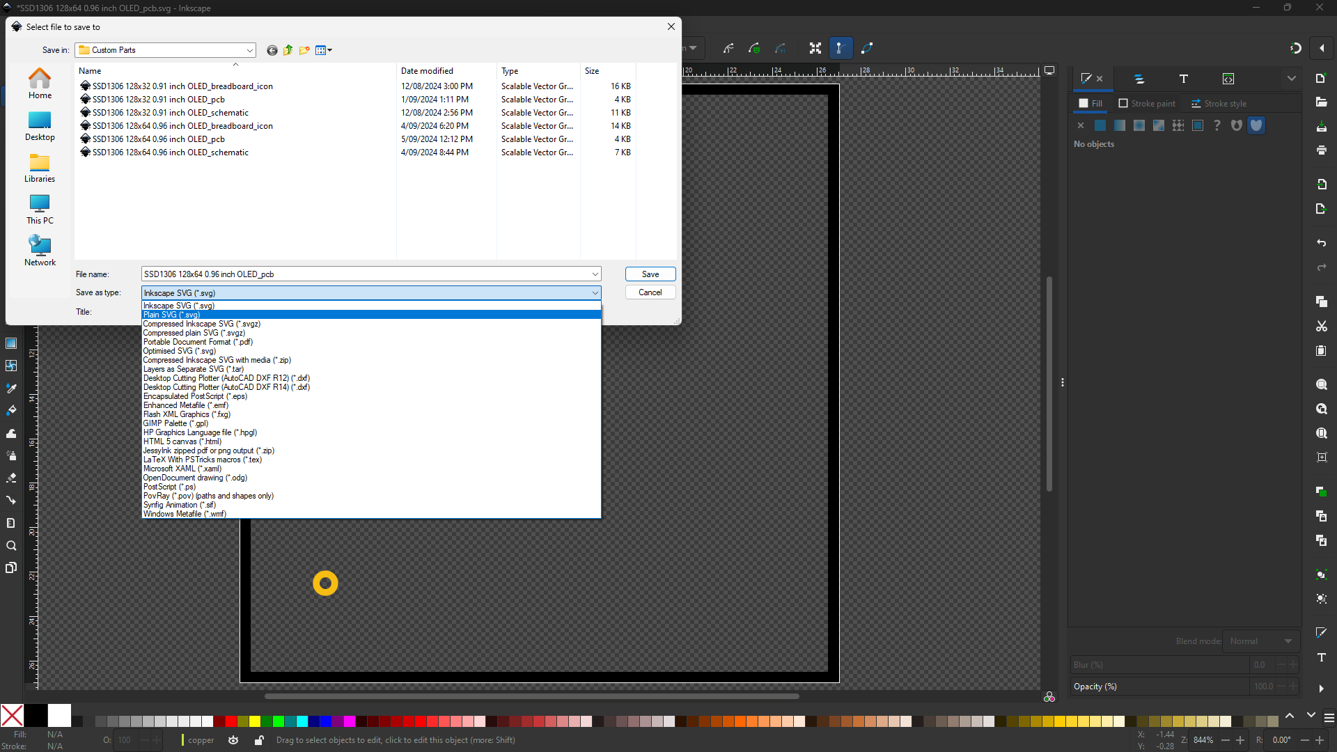
There are more resitrictions that must be followed. Please read Official guide for greater understanding. There are things to consider like distance of pins and thickness of all lines for PCB view.
Uploading Files to Fritzing
Connectors
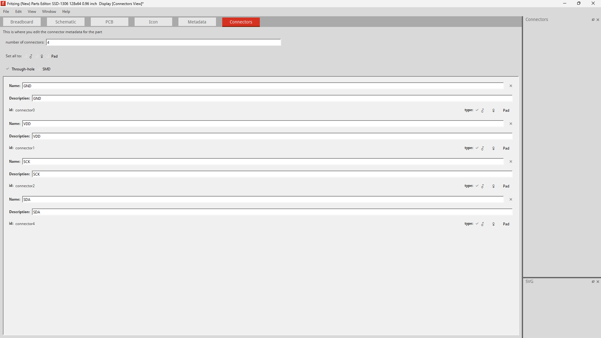
In this tab, ensure the amount of pins have been corrected and the individual names which you can add from here. You will assign the pins you have made for the Breadboard, Schematic, and PCB Viewer.
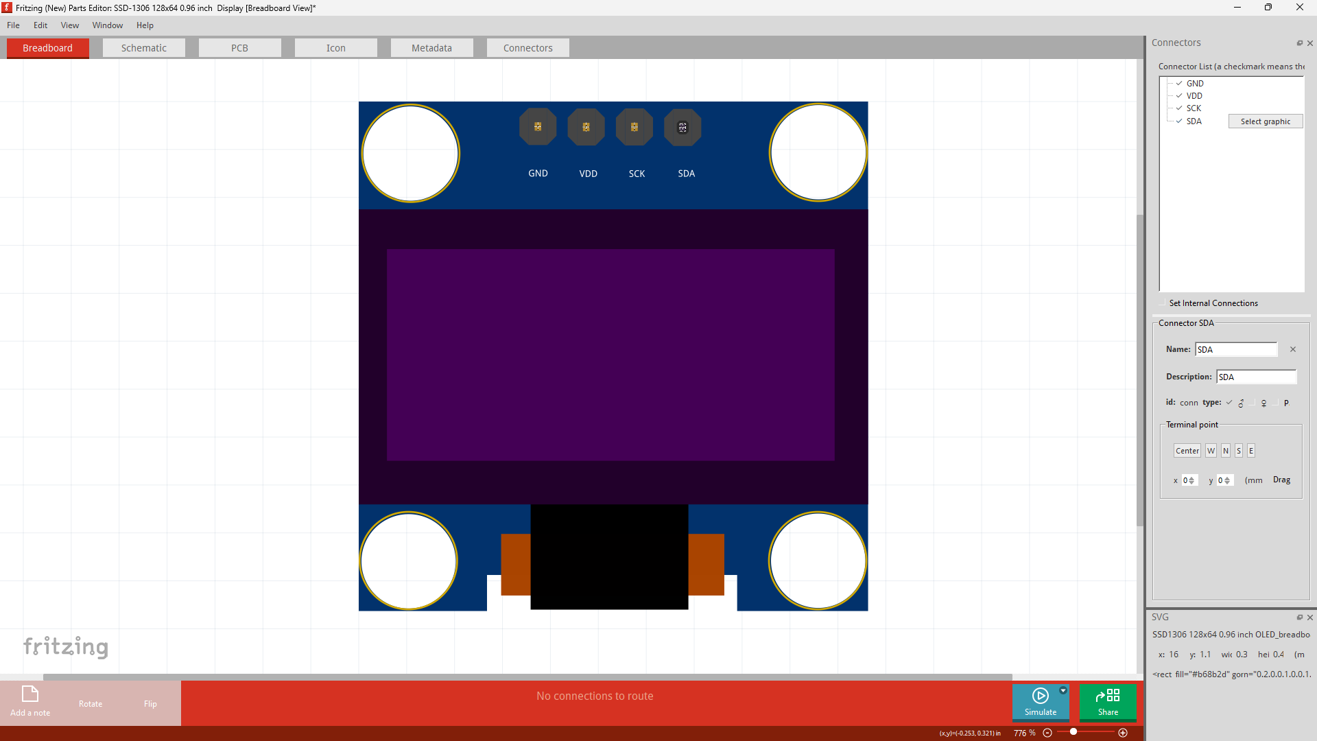
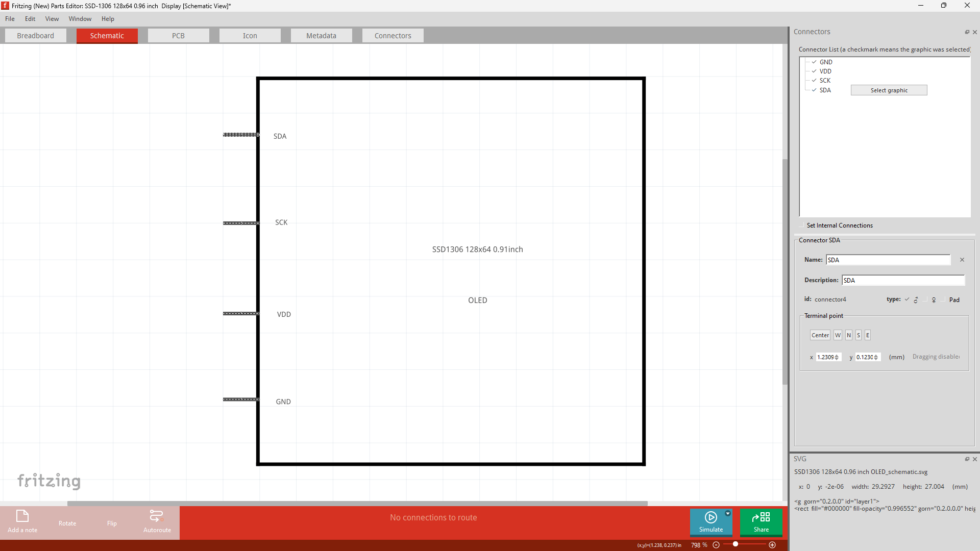
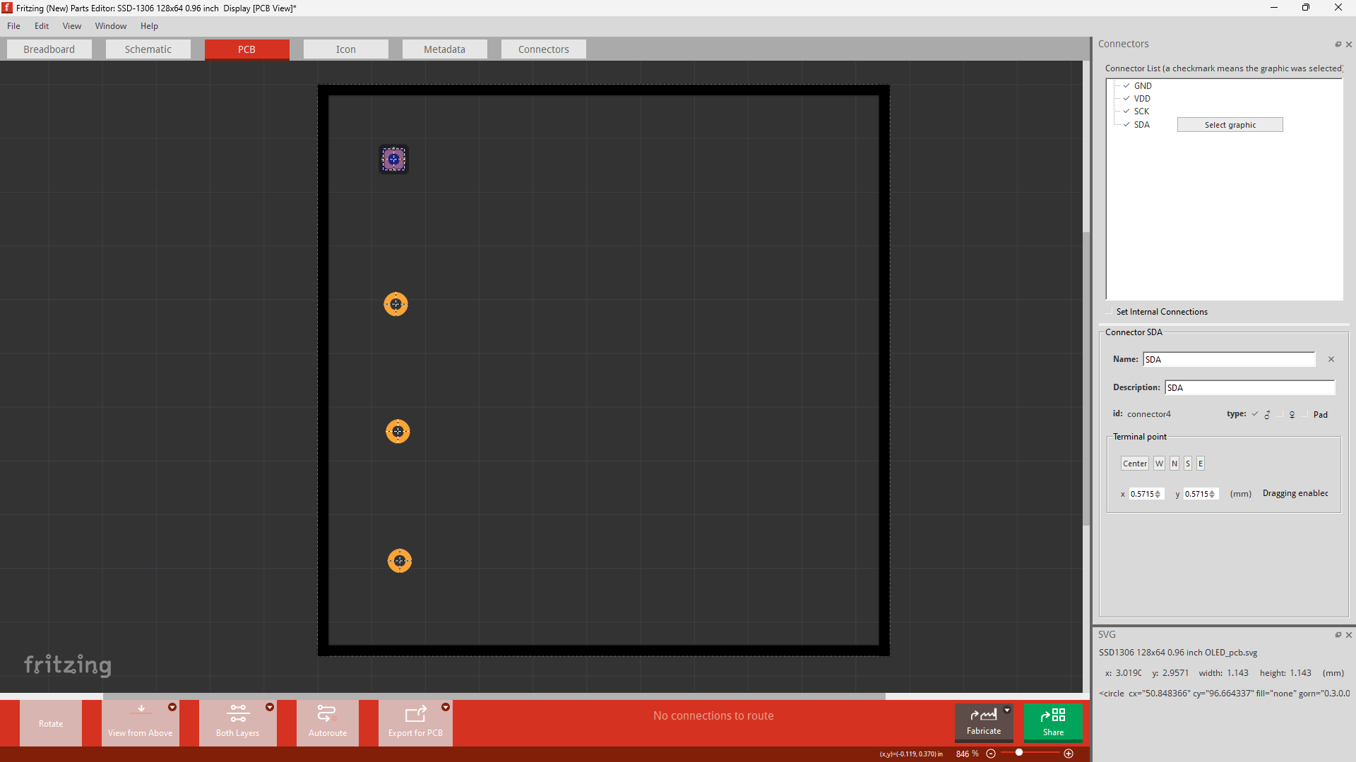
The 4 Viewers
Access the New Parts Editor, from here to upload a file click on; | File -> Load Image For View | and locate the apropraite file respective to the viewer you are on. This is the same for all views (Breadboard, Schematic, PCB and Icon).
Metadata
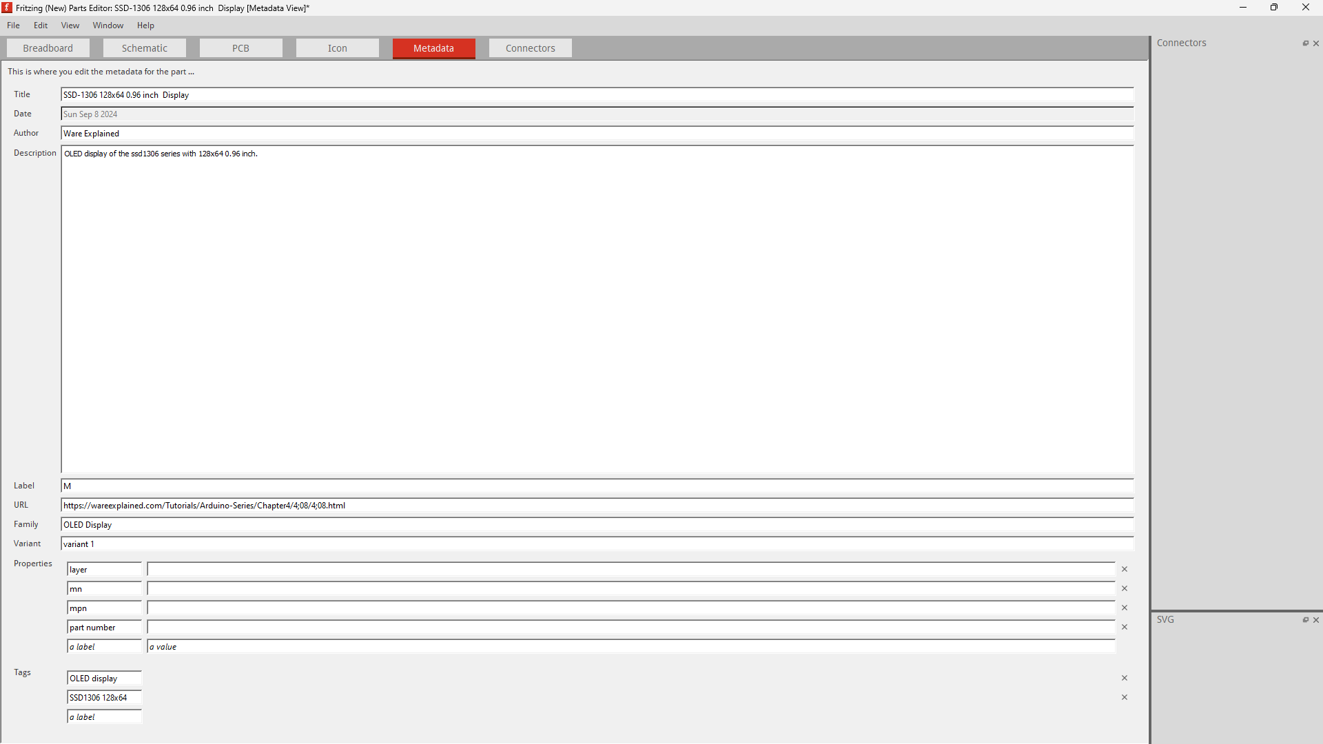
If your only objective is to make the a usable component, you can ignore everything else and only change the Title. I suggest going through it, as you've done the hard part, but as of now I will skip explaining it.
Saving the part
On the same tab, go to; file -> | save as new part | or use the shortcut | control + shift + s |
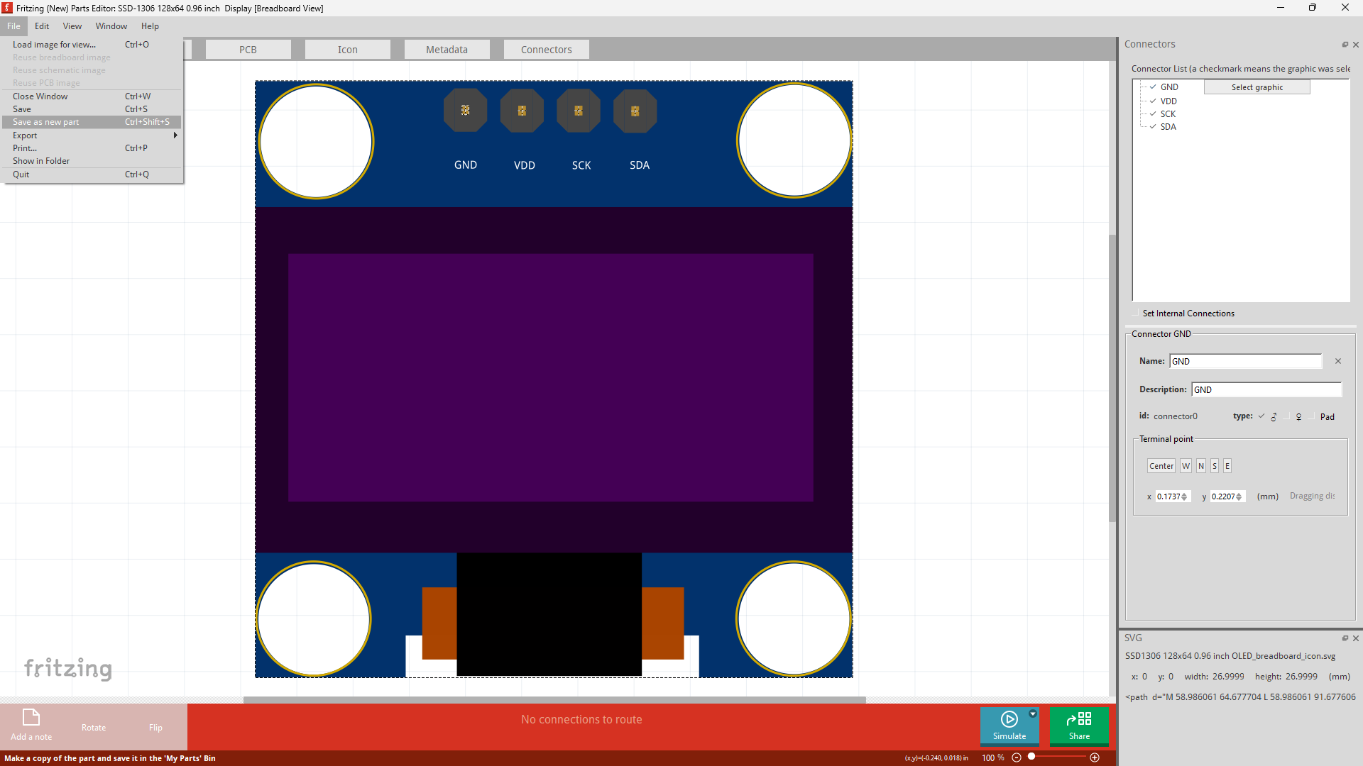
Next close fritzing. There will be 3 popups; one a warning for unsaved projects (if anything was added) and the other two associated with unsaved created new part. We only care about the latter ,all you need to do is click on "yes" for both warnings to save the new created part.
I do not where all the files regarding each part is associated. I am still looking at this to figure out how to delete a part as there is no straight forward way.